

Pilot batch processing
Filter Material
Modified polyethersulfone
Features and Advantages
High Pressure Resistance
High Temperature Resistance
Strong Anti-pollution Ability
High Throughput
Application Areas
Contact Us
Product Details
Product Applications
Cell concentration, clarification and diafiltration
Lysate clarification
VLP and virus purification, concentration and diafiltration
Protein purification, concentration and diafiltration
Nucleic acid diafiltration and concentration
Nanoparticle and latex particle diafiltration and fractionation
Bacteria concentration and diafiltration
Liposome, siRNA concentration and diafiltration
Bioreactor perfusion and media exchange
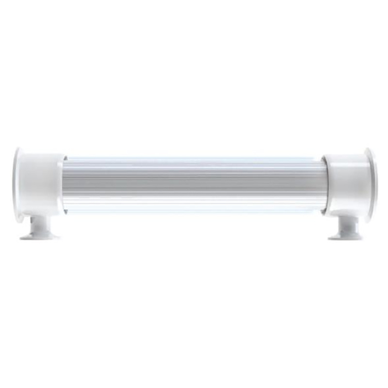
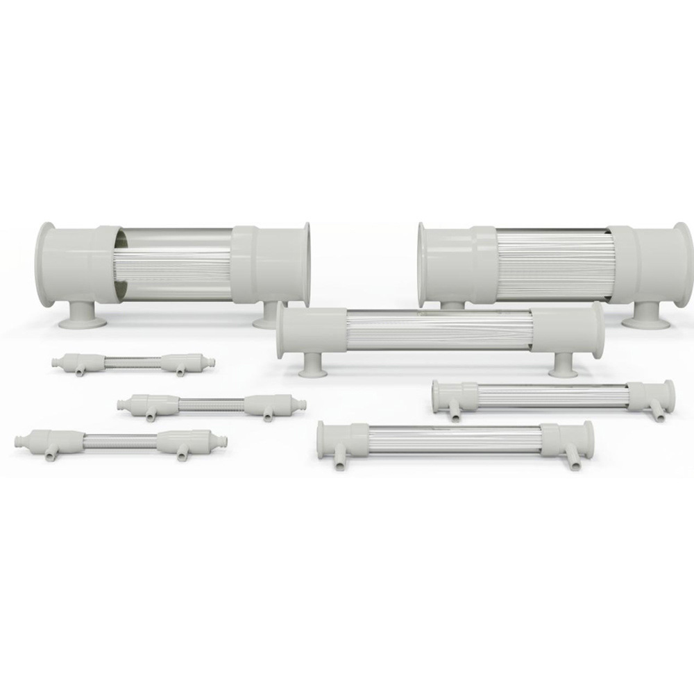
Hollow fiber filter modules are manufactured by encapsulating hollow fibers within a housing. The housing has end caps, each including two ports, totaling one feed port, one retentate port, and two permeate ports. Ports utilize different types and sizes of adaptors and fittings. The hollow fiber length is consistent with the housing, running from the feed port to the retentate port. During use, the feed liquid is pumped from the feed port under the pressure of the pump. Most of the feed liquid flows through the hollow fiber and exits from the retentate port. Another part of the feed liquid passes through the hollow fiber wall, enters the housing, and then exits from the permeate port.

Filter Component Materials
Hollow fiber membrane: Modified polyethersulfone
Support net (if any): Polypropylene
Housing, end caps and external plastic parts: Polysulfone
Potting material: Polyurethane or epoxy resin
Seals or gaskets: Platinum-cured silicone
Cross-sectional view of the hollow fiber filter module, showing the structural materials of each component of the filter module
1-Polysulfone housing and end fittings
2-mPES hollow fiber
3-Polyurethane or epoxy resin potting
4-Spectrum Label
5-Product Label

Hollow Fiber Design
The membrane used to manufacture mPES hollow fibers is seamless and structurally heterogeneous.
The dense skin layer of the mPES membrane reduces the possibility of contamination, while the relatively open outer support structure increases the filtration rate.
100X (upper image) and 750X (lower image) magnification of the hollow fiber cross-section, showing the seamless structure.

Cross-section of 30kD 0.5mm ID mPES hollow fiber, magnified 100 times

Cross-section of 30kD 0.5mm ID mPES hollow fiber, magnified 750 times
Product Performance
Low bioburden
100% integrity testing
Biocompatibility and animal-origin-free characteristics compliant with USP Class VI standards
Manufactured in an ISO Class 7 cleanroom, in accordance with ISO9001:2008 quality management system requirements
Product Series

Pilot batch processing
Permeate volume: 5 L –50 L
Fittings: 11/2”TC × 3/4”TC
Effective length: 20, 41.5 & 60 cm
Surface area: 1650 cm2–10000 cm2
Standard Water Flux
Standard water flux (NWP) is the water flow rate (LMH) divided by TMP. NWP can be calculated by dividing the actual measured LMH
by TMP. The minimum NWP requirements for different MWCO mPES filters are shown in the table below.
| 0.5mm fiber |
|
|
1mm fiber |
| mPES Hollow Fiber Specifications |
WP (L/m2H/psi)
|
mPES Hollow Fiber Specifications |
WP (L/m2H/psi)
|
| 3kD |
≥2.5 |
3kD |
≥2.5 |
| 5kD |
≥3.0 |
5kD |
≥3.0 |
| 10kD |
≥5.0 |
10kD |
≥5.0 |
| 30kD |
≥20 |
30kD |
≥20 |
| 50kD |
≥30 |
50kD |
≥30 |
| 70kD |
≥50 |
70kD |
≥40 |
| 100kD |
≥80 |
100kD |
≥60 |
| 300kD |
≥100 |
300kD |
≥100 |
| 500kD |
≥100 |
500kD |
≥100 |
Increasing the surface area of the hollow fiber filtration system
1. Increase the number of fibers
2. Increase the length of the fibers
3. Increase both the number and length of the fibers
Keywords
Pilot batch processing
Previous

Inquire Now
We will consistently provide you with high-quality filtration equipment, honest service style and the most reasonable product prices. If you have any questions, please feel free to leave a message!

Cooperate with us immediately
We focus on filtering the market, with a strict quality system and professional management model, stably producing high-quality filtering products, allowing our customers to filter with peace of mind. If you have any questions, please leave a message to consult!
Manager Geng
Manager Hu
© Copyright - 2025 Hangzhou Hexin Technology Co., Ltd.
浙公网安备33010602014027号
WhatsApp:8613858564135
WhatsApp:8619564072084
Email:service@hz-hx.cn
Email:valisanatalia373@gmail.com
Email:seller@hz-hx.cn